
MECHANICAL ENGINEERING
Hydronic Systems
Chilled water, hot water, and piping distribution layouts coordinated for accurate,
buildable hydronic systems.
Our Founding and Mission
Introduction
Hydronic systems introduce a distinct set of design and coordination challenges — pipe sizing, pump selection support, and layout routing that must account for building pressure zones and equipment room space. NexMEP Global LLC supports U.S. MEP consulting firms with hydronic system production, including chilled water and hot water piping layouts, pump and equipment room coordination, and distribution system documentation, all developed from your engineer’s system design and control narrative.
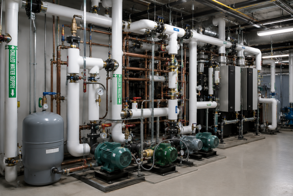
Hydronic piping layout often requires more iterative coordination than other mechanical systems because equipment rooms are typically the most space-constrained area of a building. Our team treats equipment room layout as a priority early-stage task rather than something deferred until later in design development.
DESIGN ACCURACY & COMPLIANCE
Why This Service Matters
Hydronic piping systems are typically installed in the same ceiling and shaft spaces as ductwork, electrical, and plumbing, making early and accurate coordination essential to avoiding conflicts. Pipe sizing errors or overlooked pressure drop across long distribution runs can affect system performance long after construction is complete, sometimes only becoming apparent once the building is occupied and the system is fully loaded.
Production support allows detailed piping layout and coordination work to proceed on schedule, giving your engineers a fully developed system to review rather than a preliminary layout requiring significant additional development, and reduces the risk that equipment room congestion is discovered only during construction, when changes are far more disruptive and costly.
Our Capabilities
Chilled & Hot Water Layouts
Primary and secondary loop distribution configurations, branch routing, and terminal unit connections.
Equipment Room Piping
Detailed piping arrangements for chillers, boilers, pumps, and central plant mechanical spaces.
Valving & Expansion Provisions
Piping routing engineered to account for thermal expansion, valving, and isolation standards
Phased Central Plant Tie-Ins
Clear documentation of existing piping conditions and proposed tie-in points for expansion sequencing.
Campus Utility Coordination
Interdisciplinary alignment with civil utility drawings for underground routing and building entries.
Terminal Unit Connections
Coordinated connections to fan coils, air handling units, VAV reheat coils, and radiant equipment.
Calculations
Engineering Calculations
Calculation methodology built for accurate, traceable HVAC equipment sizing.
Pipe Sizing & Flow Criteria
Pipe sizing based on flow rate and velocity or friction-loss criteria, alongside minimum flow bypass documentation for variable primary flow systems.
Pressure Drop & System Backup
Pressure drop calculations across critical distribution paths for pump verification, plus expansion tank and air separator sizing coordination.
Calculations
Systems We Support
Ventilation-related calculation support includes outdoor air rate compilation.
Two-Pipe & Four-Pipe Systems
Multi-zone piping distribution for complex HVAC configurations.
Primary-Secondary & VPF Loops
Primary-secondary and variable primary flow plant configurations.
Geothermal & WSHP Loops
Geothermal ground loops and water-source heat pump piping layouts.
Condenser Water Systems
Piping serving cooling towers, fluid coolers, and water-cooled chillers.
Glycol Freeze Protection
Specialized exposed piping design with adjusted sizing and pump specs.
Central Plant Expansion
Hydronic infrastructure connections for new and tenant improvement projects.
Our hydronic production experience covers a full range of complex central plant and distribution configurations, ensuring accurate component modeling matched to your engineer’s control parameters.
Calculations
Software, Workflow & Coordination
Rigorous backup calculations formatted directly for permit submission and QA/QC documentation.
Software & Production Workflow
Hydronic piping is modeled in Revit MEP using your firm’s piping system families and sizing parameters, developed alongside ductwork and other trade routing. Equipment room layouts are modeled early and reviewed prior to distribution piping development to optimize space constraints and ensure system alignment.
Revit & AutoCAD Coordination
Piping routing undergoes routine Navisworks clash detection against structural framing, ductwork, electrical conduit, and plumbing. We check maintenance clearance for valves, strainers, and expansion joints while coordinating structural anchor and guide locations for long pipe runs.
Calculations
Systems We Support
Expertise across diverse equipment lines, hybrid configurations, and complex mechanical setups.
Hydronic Piping Plans
Equipment Room Layouts
Piping Risers & Schematics
Calculation Backup & Schedules
Need Precise Hydronic System Documentation?
Partner with NexMEP Global LLC for fully coordinated equipment rooms, riser diagrams, and calculation support.
Our Core Philosophy
Typical Project Types
Commercial & Office
Multi-story commercial office buildings, central plants, and tenant spaces.
Healthcare & Labs
Hospitals, medical office buildings, and critical healthcare facilities.
Higher Education Campuses
Campus central plants, university buildings, and utility distribution.
Hospitality & Multi-Family
Hotels, institutional facilities, and high-rise residential complexes.
Calculations
QA/QC Process
A rigorous, multi-tiered review structure ensuring accurate, clear, and error-free submittals.
Flow Schedule Audits
Pipe sizing verified against scheduled flow rates and friction parameters.
Equipment Room Clearances
Mechanical room access and insulation thickness cross-checked against clearance rules.
Riser & Plan Cross-Checks
Secondary QA checks to guarantee pipe sizes match perfectly across plan drawings and riser schematics.
Why NexMEP Global LLC?
NexMEP Global LLC brings a dedicated production team with practical experience across standard and specialty ventilation systems, a consistent U.S. code and standards focus, and a multi-level QA/QC process that reduces rework during your engineer’s review cycle.